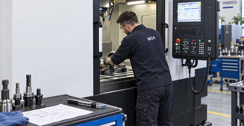

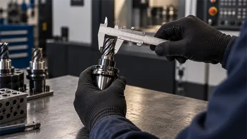
Before machining begins, the CNC system needs to know the actual geometric parameters of the installed cutting tool. CNC tool setting makes it possible to determine the tool position relative to the machine coordinate system and record the resulting values in the tool offset table. For a milling machine or machining center, this primarily means tool length and, where required, diameter or radius. On turning equipment, the geometric offsets of the cutting tip along the X and Z axes are determined, while some operations also require the tool nose radius and its orientation to be taken into account.
This is not the same as setting the workpiece coordinate system. In the first case, the CNC system receives information about the tool; in the second, it receives information about the position of the workpiece relative to the machine. Machine coordinates, the work zero point, and tool offsets are used together when calculating the actual toolpath, but they describe different parameters. Therefore, a measurement reference point or surface used during tool setting does not automatically become the workpiece zero point.
Correctly entered values are required to ensure that the cutting edge reaches the position specified by the CNC program. An error in tool length or a geometry offset shifts the actual machining path, while an incorrectly accounted clearance between the tool and the workpiece or fixture increases the risk of collision.
Methods of measuring tools on the machine
The manual method is based on moving the tool toward a known surface or calibrated measuring element. The operator monitors contact, reads the axis position, and enters the resulting value into the tool offset table according to the procedure specified for the particular machine and CNC system. Calibrated plates, gauge blocks, indicators, or probes can be used for this purpose. A sheet of paper can be used as a simple setup technique for detecting the point of contact, but it is not a precise industrial measuring method.
The automatic method uses a measuring sensor installed within the machine working area. When the tool makes contact with the sensor, the system registers the trigger signal and calculates the required tool parameter based on the axis position and the previously calibrated position of the measuring device. One example is the Renishaw TS27R, which can be used to measure tool length and diameter as well as detect tool breakage.
The measurement result is affected by system calibration, machine condition, sensor repeatability, and the cleanliness of the contact surfaces. For this reason, measurement error cannot be specified as one universal value for all machines and operating conditions.
Contact and laser measurement: what is the difference?
With the contact method, the tool is moved toward the measuring surface of the sensor until it is triggered. The system records the axis position and, using the calibrated parameters of the measuring device, determines the tool length, diameter, or radius. Measurement cycles provided by the machine and CNC system manufacturer are used for this purpose.
Laser measurement is a non-contact method. The cutting portion of the tool passes through a laser beam between a transmitter and receiver, and the system detects when the beam is interrupted and calculates the required parameters. Systems such as the Renishaw NC4 and NC4+ Blue operate according to this principle. Depending on their configuration, they can be used to measure tool geometry and detect tool breakage.
The main difference is the way the measurement signal is obtained: with contact measurement, the tool physically interacts with the measuring surface, while laser inspection is performed without mechanical contact.
Features of milling and turning machines
Tool setting on a CNC milling machine usually includes determining tool length and, where necessary, diameter or radius. The actual projection of the complete tool assembly from the holder is important: after replacing the holder, reassembling the tool, or reinstalling it, its geometric parameters may change. For milling cutters and other rotating tools, these values are recorded in the appropriate tool offset tables. CNC drill setting is required so that the system correctly accounts for the position of the drill tip and maintains the specified machining depth.
The same general principle applies to horizontal machines and vertical machining centers, but the specific procedure depends on the machine design. The spindle, table, pallet, and other units determine the machine kinematics, so the measurement cycle and the procedure for recording the resulting values must comply with the manufacturer's documentation.
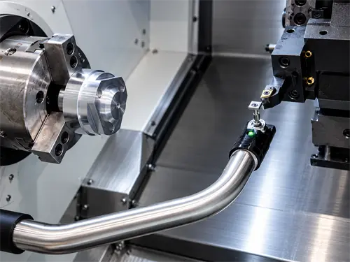
Tool setting on a CNC lathe is primarily associated with determining the position of the cutting edge along the X and Z axes. One common manual method is to make a trial turning cut, measure the resulting diameter, and use the result to determine or refine the geometry offset along X. A trial facing operation can be used to determine the position along Z, followed by recording the corresponding coordinate.
This principle is used on machines in the turning centers and vertical turning categories. If the equipment is fitted with an automatic tool measurement system, some of these operations can be performed using dedicated measurement cycles. The turret indexes the required tool into the working position, while the exact tool setting procedure depends on the machine design, CNC system, and manufacturer's recommendations.
Why one instruction cannot be used for every CNC system
The CNC control stores tool offset tables and, depending on the machine configuration, can perform automatic measurement cycles. However, the interface, menu structure, cycle calling procedure, and logic for recording values differ between control systems and individual machine models. FANUC and Siemens CNC systems are widely used on industrial machines, but even the same CNC platform does not guarantee an identical tool setting procedure on different machines.
The machine manufacturer adapts macros, signals, measurement cycles, and auxiliary functions to the specific machine design and configuration. For this reason, a universal sequence of button presses is not reliable for every machine. Tool measurement and the recording of measured values in the offset table should be performed in accordance with the documentation for the specific machine model, installed CNC system, and software version.
Presetting tools outside the machine
A tool can be assembled in its holder and measured on an external presetter before it is installed in the machine. This makes it possible to determine the actual geometric parameters of a specific tool assembly, such as its length and diameter or radius. The resulting values can then be transferred to the CNC tool offset table manually or through a data transfer system. This approach is particularly convenient for frequent changeovers and for preparing several tool sets in advance.
If the holder is changed, the tool is resharpened, or the composition of the tool assembly is modified, the original data must be checked and updated where necessary. External measurement reduces machine preparation time, but it does not eliminate the need for correct tool installation and verification of its parameters after installation.
How to account for parameter changes and when to measure again
Initial tool geometry values and wear compensation serve different purposes. Geometry offsets describe the actual dimensions and position of the installed tool, while wear compensation is used to compensate for small changes in the cutting edge during operation without repeating a full geometry measurement.
Repeated measurement or an additional check may be required whenever there is reason to expect a change in the dimensions or position of the tool:
- after installing a new tool;
- after replacing an insert, holder, or complete tool assembly;
- after resharpening or restoring the cutting portion;
- after a collision or another abnormal event;
- when a consistent dimensional deviation is detected on the workpiece;
- before a critical production batch when the condition of the tool needs to be confirmed.
The appropriate verification method depends on the reason for the change: in one case, a complete remeasurement of the tool geometry may be required, while in another, checking the workpiece and adjusting the wear offset may be sufficient. The main factor is not the amount of time that has passed, but an actual change in the position, geometry, or condition of the cutting edge.
How to choose a tool setting method
The tool setting method is selected according to the type of machine, range of tools, accuracy requirements, changeover frequency, and level of production automation. Contact measurement is suitable for a wide range of tools and applications, laser measurement provides inspection without mechanical contact with the cutting portion, and an external presetter moves part of the measurement process outside the machine working area.
The size and type of tool, required measurement repeatability, equipment preparation time, and the possibility of automatically transferring data to the CNC system should also be considered. For one production environment, manual or contact measurement directly on the machine may be optimal; for another, a combination of an external presetter and automatic in-machine tool inspection may be more appropriate.
The effectiveness of the selected method depends not only on measurement accuracy, but also on result stability, changeover speed, and ease of use within the specific manufacturing process. When specifying new equipment, it is advisable to select the measurement system together with the machine and its tooling package. The specialists of TECHNICAL CLUSTER LLC help select WIA Machine Tools equipment and measurement solutions for specific production requirements and also provide support with installation, commissioning, personnel training, and ongoing service.