
The selection of metalworking equipment begins with an analysis of the production task. CNC machines may use the same general principle of programmed control, but their design, kinematics, and technological capabilities can differ significantly. Therefore, such classification makes it possible to match part geometry, the required operations, production volume, and target productivity with the capabilities of specific equipment.
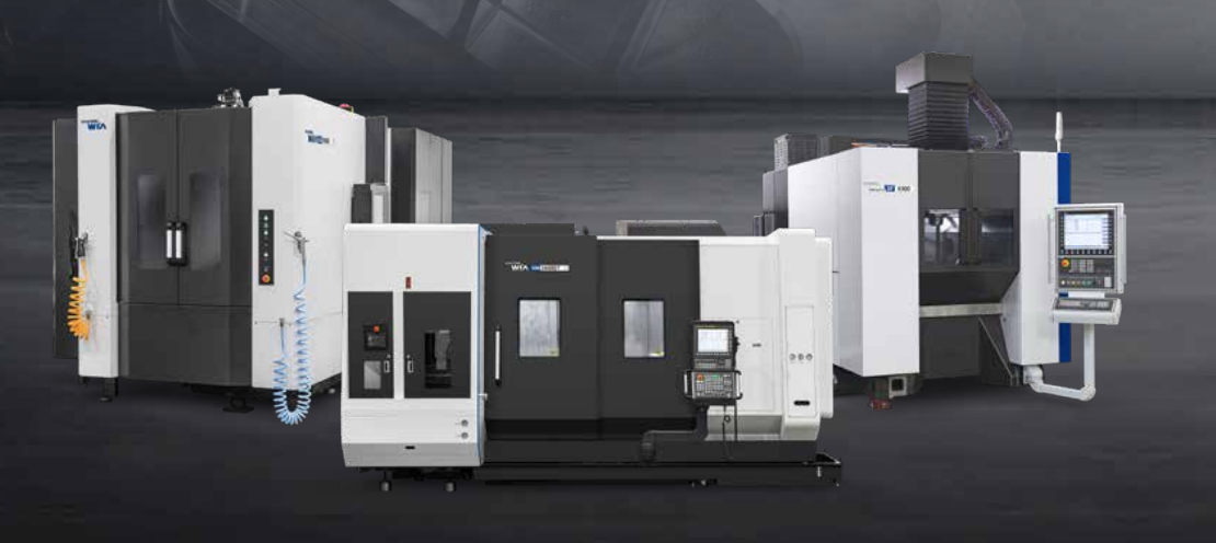
In practice, different types of CNC machines are usually classified primarily by technological purpose, machine configuration, the number and type of controlled axes, and the level of automation. These characteristics determine why a turning center is selected for machining shafts, a vertical or horizontal machining center for prismatic and housing-type parts, and a five-axis or turn-mill configuration for more complex geometries.
Which criteria are used to classify CNC machines
A single criterion does not provide a complete picture. For example, two vertical machining centers may have the same general configuration but differ in the number and type of controlled axes, working area, spindle characteristics, and level of automation.
When classifying CNC machines, the following factors are usually considered:
- technological purpose and the main machining operations performed;
- machine configuration, spindle orientation, and arrangement of the main working units;
- the number and type of linear and rotary axes;
- working area dimensions and allowable workpiece parameters;
- the ability to combine several types of machining;
- the level of automation and additional equipment.
This approach helps determine which kinematic layout and machine configuration best match the geometry of the parts, the manufacturing process, and the requirements of a specific production environment.
What components make up a CNC machine
A CNC machine is an integrated electromechanical system. The controller interprets the machining program and generates commands for the drives, while the mechanical units provide the required movements and cutting process. Therefore, the capabilities of the equipment depend on the coordinated operation of the control system, drives, spindle, measuring devices, and load-bearing structure.

Depending on the machine type and configuration, its main components may include:
- bed, column, carriage, worktable, and other structural components;
- spindle unit providing rotation of the cutting tool or workpiece;
- servo drives for the controlled axes;
- guideways and motion transmission mechanisms;
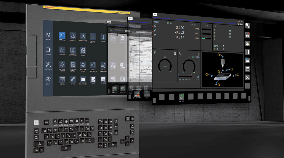
- CNC system and operator panel with display;
- measuring devices used to monitor axis position;
- auxiliary systems for tool changing, coolant supply, and chip removal.
Inside the controller, a microprocessor processes programmed commands and performs the required calculations, including trajectory interpolation. The system memory is used to store machining programs, machine parameters, offsets, and other technological data.
Classification of CNC systems by type of movement
According to the way movement is controlled, CNC systems can be divided into positioning and contouring systems. Positioning systems move a machine unit to specified coordinates, after which the technological operation is performed. The path between the points does not define the machined surface, so this principle is used where reaching a specific position is important, for example in drilling operations.
Contouring, or continuous-path, systems control the coordinated movement of several axes directly during machining. The controller calculates intermediate coordinates and maintains tool movement along the programmed trajectory. This mode is used for profile turning, contour milling, and multi-axis machining.
In modern industrial CNC systems, positioning and various types of interpolation are usually combined within the same controller. Therefore, this classification primarily describes the method of motion control rather than separate classes of electronic systems.
Open-loop and closed-loop control systems
Another classification criterion for CNC systems is the presence of feedback. In an open-loop system, the movement command is sent to the drive without continuous monitoring of the actual position of the moving unit. In a closed-loop system, sensors transmit information about the movement to the control loop, allowing commanded and actual values to be compared. Modern industrial metal-cutting machines typically use servo control with feedback.
Systems may also operate as standalone solutions on an individual machine or be connected to a production network for transferring programs and technological data. Such connectivity expands equipment integration capabilities but does not change the basic principle of machining program execution.
How CNC converts a program into tool movement
Machine operation begins with the preparation of a machining program. For simple operations, the program can be created directly at the CNC control, while CAD/CAM systems are commonly used for more complex geometries. A postprocessor generates code that takes into account the kinematics of the specific machine and the requirements of its control system.
In simplified form, the process works as follows:
- part geometry, cutting tools, feed rates, spindle speeds, and other machining parameters are defined;
- the postprocessor generates code compatible with the specific CNC system and machine kinematics;
- the controller performs trajectory interpolation and sends commands to the servo drives;
- the measuring system monitors the actual axis positions, while auxiliary commands control the spindle, tools, and coolant supply.
G-code is widely used for CNC programming, but the specific command set and its implementation depend on the CNC system and machine manufacturer. Therefore, even when generally accepted standards are used, the machining program must be adapted and verified for the specific machine.
Main types of machines by technological purpose
In metalworking, one of the main classifications is based on the nature of the machining operations and the geometry of the parts. It determines which machine unit rotates, how the workpiece is positioned, and which surfaces can be machined in a single setup.

The main groups include:
- turning machines for shafts, bushings, flanges, and other rotationally symmetrical parts;
- vertical and horizontal machining centers for prismatic parts, plates, slots, holes, and other features;
- five-axis machining centers for parts with complex spatial geometry and multi-sided machining;
- multipurpose turn-mill solutions that combine turning and milling operations on one machine.
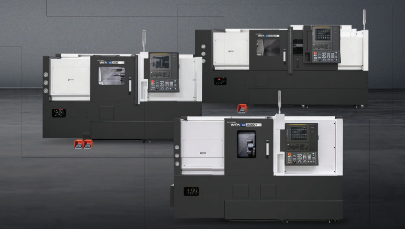
Turning centers are primarily used for machining rotationally symmetrical parts. Vertical machining centers are suitable for a wide range of prismatic parts, plates, tooling, and molds. Horizontal machining centers are particularly effective for multi-sided machining of gearbox housings, hydraulic blocks, pump housings, and other complex prismatic components. Five-axis machines are used where it is necessary to change the orientation of the tool relative to the workpiece and reduce the number of setups.
Turn-mill and other combined solutions are selected when several different types of operations can be efficiently performed in a single setup or on one machine. The specific machine type is determined not by its general category name, but by part geometry, the required operations, and productivity requirements.
How CNC turning machines are classified
CNC turning machines are classified according to several criteria at the same time: machine layout, number of spindles and working units, availability of driven tooling, additional controlled axes, and automation equipment. When comparing different types of CNC turning machines, their basic task remains the same — machining rotationally symmetrical parts in which the workpiece rotates relative to the cutting tool.
The main configurations include:
- horizontal turning centers for shafts, bushings, flanges, and other rotationally symmetrical parts;
- vertical turning centers for large and heavy workpieces with large diameters;
- twin-spindle machines that allow both sides of the part to be machined with automatic transfer between spindles;
- turn-mill configurations with driven tooling and a C-axis and, depending on the configuration, also a Y-axis;
- multi-axis configurations for parts that require a combination of several machining processes.
These characteristics can be combined in the same machine. For example, a turning center may simultaneously have two spindles, driven tooling, and a Y-axis, so the final configuration is determined by the manufacturing process of the part.
When selecting turning centers, important parameters include maximum workpiece diameter and length, spindle bore, power and torque, the set of controlled axes, the number of turret stations, and automation capabilities. For serial production, bar feeding, parts catchers, chip removal, and robotic loading are also important.
What types of CNC milling machines are used in production
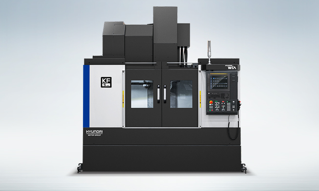
For milling equipment, one of the main differences is the spindle orientation and overall machine configuration. A vertical layout is suitable for a wide range of operations on prismatic parts, plates, tooling, molds, and other components. Vertical machining centers differ in worktable dimensions, axis travels, guideway type, spindle characteristics, and the number of controlled axes.
In a horizontal configuration, the spindle is positioned parallel to the surface of the worktable or pallet. This arrangement is particularly effective for multi-sided machining of prismatic parts, while chips are more easily removed from the cutting zone under their own weight. Horizontal machining centers may be equipped with rotary pallets, automatic pallet changers, and different configurations for high-productivity and heavy-duty machining.
Five-axis machining centers typically combine three linear axes with two rotary axes. This kinematic arrangement makes it possible to change the orientation of the tool or workpiece and machine parts with complex spatial geometry while minimizing the number of setups. This reduces the influence of repeated workpiece positioning on accuracy and simplifies the overall manufacturing process.
How turn-mill centers differ from specialized machines
Turn-mill centers combine operations that would otherwise have to be performed on several specialized machines. Turning remains the primary machining process, while driven tooling and a controlled C-axis make it possible to perform drilling, milling of slots and flats, and other operations. Depending on the configuration, the machine may also be equipped with a Y-axis, sub-spindle, and additional automation equipment.
Turn-mill machines are selected when a significant part of the manufacturing process can be efficiently completed in a single setup. Reducing transfers between machines decreases non-cutting time and minimizes the influence of repeated workpiece positioning on the accuracy of relative surface locations.
However, a combined configuration is not necessary for every part. If the manufacturing process consists mainly of simple repetitive operations, a specialized turning or milling machine may be a more efficient solution in terms of productivity and machining cost.
How the number of axes affects technological capabilities
Three linear axes — X, Y, and Z — form the basic kinematic configuration of many milling machining centers. Rotary axes A, B, and C make it possible to change the orientation of the tool or workpiece relative to one another and expand the capabilities for multi-sided and spatial machining.
Increasing the number of controlled axes can reduce the number of setups and provide access to more complex geometries, but it also increases the complexity of the machine kinematics, programming, and technological preparation.
When selecting equipment, the number of axes itself is not the main criterion. The configuration must correspond to the specific part. The working area, allowable workpiece weight, tool dimensions, kinematic limitations, CNC system capabilities, and required productivity must all be taken into account. A three-axis machining center with properly selected tooling and fixtures may be more efficient than a more complex machine if the part geometry does not require additional axes.
What to consider when selecting a machine type
Proper optimization of a production area begins with an analysis of the parts and their manufacturing process. Even similar components may have different requirements for material, accuracy, productivity, and level of automation.
Before selecting equipment, it is necessary to determine:
- the material and specific metal grade, as well as its machining characteristics;
- the dimensions, weight, and shape of the initial workpiece;
- the required machining operations and their sequence;
- the required tolerances and surface quality;
- the planned production volume and required productivity;
- the need to machine several planes and sides of the part in a single setup;
- requirements for automatic loading, part and tool measurement, and chip removal;
- the required protection of the working area and operational safety requirements.
The nature of the machining process should also be considered. For heavy roughing, structural rigidity, spindle power and torque, and the ability of the guideways to withstand high loads are especially important. For high-productivity and accurate finishing, spindle speed, axis travel speed, machine thermal stability, and efficient coolant system operation become more important.
These requirements should preferably be defined in the technical specification in advance and then compared with the characteristics of a specific machine. This approach reduces the risk of selecting equipment with excessive capabilities or, conversely, limitations that only become apparent after production has already started.
How to select a WIA Machine Tools configuration for a company's production requirements
TECHNICAL CLUSTER is the official representative of WIA Machine Tools in Ukraine and works with the manufacturer's turning, vertical, horizontal, and other machining centers. The machine model and factory configuration are selected according to the technical specification, part geometry, required operations, productivity targets, and level of automation.
The company's specialists analyze the initial technological data and compare it with the capabilities of suitable WIA Machine Tools series. Project support includes equipment selection, delivery, installation, commissioning, personnel training, and service support.
The basic principle of selection is not to determine which machine class is better in general, but which equipment can provide the required result for the specific manufacturing process. To prepare a proposal, customers can provide TECHNICAL CLUSTER specialists with part drawings, material information, planned production volume, required accuracy, and the main machining operations.