

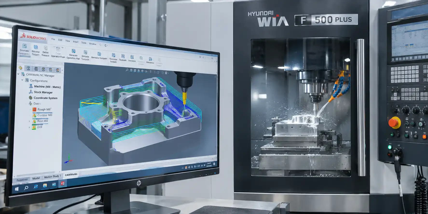
When manufacturing a part on a CNC machine, the result depends not only on the drawing and the capabilities of the equipment. The machining sequence must be defined: the tools selected, cutting conditions specified, toolpaths calculated, and their movement through the working area checked. These tasks are part of CNC machine programming.
The CNC program defines the movement of the tool or workpiece along the controlled axes, spindle speed, feed rate, tool changes, and other commands. The CNC system interprets these commands, controls axis movements and spindle operation, and interacts with other machine systems. Proper program preparation affects part accuracy, surface quality, cycle time, and machining safety.
This article explains the main methods used to create CNC programs, the role of CAD/CAM systems, and the preparation of programs executed by turning and milling machines.
What a CNC program provides
A CNC program converts a machining process plan into a sequence of commands understood by the CNC system. It defines coordinates and movements, the sequence of operations, machining parameters, tool operation, and auxiliary machine functions.
CNC programming makes it possible to reproduce a defined sequence of operations and movements from one part to the next. On equipment such as turn-mill centers, this is especially important in series production: if the workpieces, tooling, cutting tools, and clamping conditions correspond to the approved setup, the machine can repeat the same machining cycle. Process stability also depends on the condition of the equipment, correct setup, tooling, and process control.
A CNC program can:
- define linear and circular movements;
- control tool changes or indexing and execute machining cycles when these functions are supported by the machine design;
- machine contours, holes, threads, shoulders, and other features;
- repeat a verified sequence of operations across a series of workpieces;
- coordinate the movement of multiple axes and the operation of automated machine units.
These capabilities reduce the amount of manual intervention during the machining cycle and help maintain the required sequence of operations. Before starting the machine, it is necessary to confirm that the program, tools, machining parameters, workpiece, and clamping method correspond to the prepared process and setup.
Basics of CNC code preparation
CNC programming generally includes defining the geometry of machine movements and the technological parameters of the machining process. G-codes and other commands and functions supported by the specific control system are used for this purpose. The available commands, their syntax, and their behavior may differ depending on the CNC system, its version, and the machine configuration, so the program should be prepared according to the documentation for the specific machine and control system.
The word “code” is often used as a general term for the commands contained in a CNC program. These commands may define axis movements, feed rate, spindle speed, tool selection and change, coolant operation, other auxiliary functions, and transitions between machining stages.
Writing CNC code requires an understanding of the drawing, machining technology, and the conditions under which the program will run on the machine. An incorrect coordinate, an incorrectly defined work coordinate system, or an incorrect tool offset can result in a defective part or a collision between the tool, workpiece, and fixtures. Code preparation therefore always involves checking the program logic, input data, and execution conditions.
Manual programming and CAD/CAM systems
For a simple part, a short program may sometimes be written manually, either directly on the CNC control panel or in an editor. Manual programming can be convenient for simple operations, standard cycles, and minor adjustments when the toolpath can be easily followed from the drawing.
CNC milling programs are often prepared using CAD/CAM systems. CAD is used to create or open the geometric model of the part, while CAM is used to plan the machining process, select operations, and calculate toolpaths. A postprocessor then converts the prepared toolpaths into a CNC program that takes into account the specific machine model, CNC system, kinematics, and configuration. This approach is particularly useful for complex contours, multi-axis machining, and parts whose toolpaths would be difficult to define reliably by hand.
Two main approaches are commonly used:
- Manual CNC program writing.
- Program preparation using a CAD/CAM system.
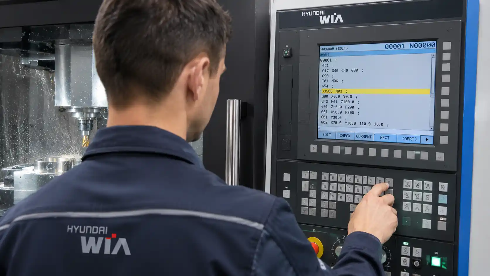
In practice, these approaches are often combined. For example, the main toolpath and CNC program may be generated in a CAM system, after which a specialist makes permitted edits to the program or adjusts individual technological values according to the procedures used by the company.
The choice of method depends on part complexity, accuracy requirements, available software, machine configuration, and the qualifications of the team. The program preparation method should match the capabilities of the specific machine and be understandable to the specialists responsible for setup, verification, and startup.
How a CNC program is created
The process begins with input data: a drawing or 3D model of the part, the material and dimensions of the workpiece, and requirements for tolerances, surface finish, and productivity. Based on these data, the sequence of setups and operations is determined, tools are selected, and machining parameters are assigned.
When working in a CAM system, the specialist defines the stock, tools, and machining operations and calculates the machining toolpaths. The CNC program is then generated using the appropriate postprocessor.
Before the program is transferred to the machine, it should preferably be checked using the available simulation tools. Simulation can reveal some problems before the equipment is started, including unnecessary or unsafe movements, possible collisions, an incorrect machining direction, or an unsuitable sequence of operations. The reliability of the simulation depends on the accuracy of the digital models of the machine, tools, workpiece, and fixtures.
The first run of a new or modified program is performed in a controlled manner using the verification tools and modes provided by the machine manufacturer and CNC system, such as step-by-step execution, movement speed control, and other available functions. After the first part has been produced, its dimensions and machining result are checked. Permitted corrections are made when necessary, followed by another program check.
Turning and milling operations
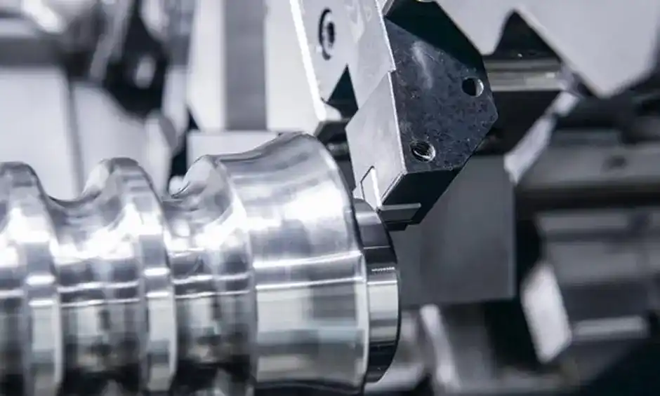
When programming turning operations, the part profile, sequence of turning, drilling, threading, and other operations, as well as the machining parameters for each operation, are defined. CNC lathe programming is based on the rotation of the workpiece and movement of the cutting tool relative to it. On more advanced turning and turn-mill centers, the program may also account for driven tooling, additional axes, a sub-spindle, and synchronization between individual machine units.
On milling equipment, the cutting tool rotates while its relative movement with respect to the workpiece is generated by the controlled machine axes. CNC part programming may include face and contour milling, pocket machining, drilling, and other operations. The ability to machine several sides of a part in one setup depends not only on whether the machine has a vertical or horizontal configuration, but also on its kinematics, rotary axes, table, pallet system, and workholding equipment.
For more complex combined machining, 5-axis turning centers and other multi-axis configurations may be used. Depending on their design, they can combine turning and milling operations and use driven tools, additional controlled axes, and a sub-spindle.
The more axes and automated units involved in the process, the more carefully the toolpaths and interaction between mechanisms must be checked. Parametric programming may be suitable for parts that differ in dimensions but share recurring geometry and the same sequence of operations. Dimensions, feature positions, or other defined values can be set through variables when this approach is supported by the specific CNC system and is appropriate for the task. This method can be used, for example, when preparing programs for series of parts on CNC turning machines.
Errors, verification, and startup
Even a toolpath correctly calculated in a CAM system does not guarantee correct machining if the input data or the actual machine setup differs from the assumptions used during program preparation. Common causes of problems include an incorrectly defined work coordinate system, errors in tool geometry or offsets, an unsuitable postprocessor, incorrect input data, and missing auxiliary commands.
Before startup, it is useful to follow a verification checklist:
- compare the program with the drawing and process plan;
- check the measurement units, work coordinate system, and part zero position;
- verify that the installed tools and required geometric offsets match the data in the CNC system;
- review the toolpath in simulation and check safe movements;
- confirm that the workpiece and fixtures are installed according to the setup sheet;
- perform a controlled program check using a mode provided for the specific machine and carefully monitor the initial movements.
The accuracy of the finished part depends on more than the CNC program alone. The condition and accuracy of the equipment, cutting tools and their offsets, workpiece clamping, correct setup, and selected machining parameters all affect the result. Therefore, the CNC programmer, setup technician, and operator must consider not only the calculated toolpath but also the actual machining conditions. Stable series production requires properly functioning equipment, a verified setup, and inspection of the first parts.
When introducing new equipment, the team needs technical consultation, training, and service support. TECHNICAL CLUSTER LLC, the official representative of WIA Machine Tools in Ukraine, supports manufacturers from machine selection through installation, commissioning, and personnel training. Its specialists help match production requirements with equipment capabilities and define requirements for automation and CNC program preparation.